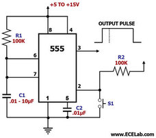
Figure 1. Switch Debouncing Circuit Diagram Using the 555 Timer
This is a switch debouncing circuit that employs a 555 timer IC. One problem with any pushbutton switch is the oscillation that occurs when it makes electrical contact to close the circuit. This can result in 'bounces' or undesired multiple pulses that can lead to errors in digital circuits.
The circuit above can be used to 'debounce' a pushbutton switch. It gets its initial trigger from the pushbutton switch and outputs a single clean pulse that the receiving circuit can use error-free. In this circuit, the 555 timer is essentially configured as a 555 monostable multivibrator.
The circuit above can be used to 'debounce' a pushbutton switch. It gets its initial trigger from the pushbutton switch and outputs a single clean pulse that the receiving circuit can use error-free. In this circuit, the 555 timer is essentially configured as a 555 monostable multivibrator.
 RSS Feed