| The IC 555 is used widely in different types of alarm circuits. Let us try to understand one of these circuits, which can be used for light detection.Circuit Design A 50 kilohm resistance is connected between Pin 8 and Pin 7 and a 1 kilohm resistance is connected between Pin 7 and Pin 6. Pin 2 is shorted to Pin 6. The positive terminal of a 0.047 microfarad capacitor is connected to Pin 6 and the other end of the capacitor is grounded. The speaker is connected to the output Pin 3 through a 4.7 mircofarad capacitor. The other terminal of the speaker is grounded. For detecting light, an LDR (Light Dependent Resistor) is used. The LDR is connected between Pin 5 and Pin 8 using DPDT (Double Pole, Double Throw) switch.Another DPDT switch is connected in between Pin 4 and Pin 8 with a 10 kilohm resistance in between. Finally we connect Pin 8 to the 5 Volt power supply and Pin 1 is grounded. Now, whenever the LDR is exposed to direct light or when the LDR is place in complete darkness, the speaker will produce an alarm. What is explained above, is a simple alarm circuit using the 555 timer. IC 555 can be used similarly, in major alarm systems. The 555 timer applications that have been explained in this article, are the miniature versions of their actual applications. The circuits are used in large numbers by major consumer electronics goods manufacturers. Using this IC simply eliminates the need of an external timer circuit. | 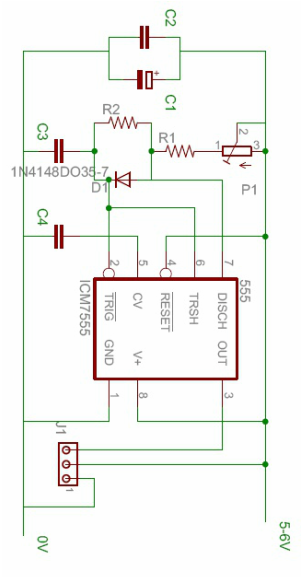
|
1 Comment
Ian Weber
12/1/2012 06:04:30 pm
What is the student learning for this post? Information focused not student focused Leave a Reply. | about usWe are Khaled Alanzi and Abdulrhman and we study in TTC riyadh and we specialization in electronics Categoriescontact us
|
 RSS Feed