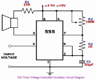
This experience on applications Ic555 and tells about how to use Ic555 the radio circuits.

  • What was the main point of the video?

 
The twin T notch filter can be used block an unwanted frequency or if placed around an op-amp as a bandpass filter. The notch frequency occurs where the capacitive reactance equals the resistance (Xc=R) and if the values are close, the attenuation can be very high and the notch frequency virtually eliminated. The insertion loss of the filter will depend on the load that is connected to the output, so the resistors should be of much lower value than the load   for minimal loss.
 
  At audio frequencies, the filter could function as a bass and treble boost circuit by attenuating the mid range frequencies. Using 1.5K 
resistors and 0.1uFcapacitors, the band stop at -10dB is about 500 Hz to 2Khz. The depth and width of the response can be adjusted
somewhat with the 0.5R
value  and by adding some resistance across the C values.
 
Picture
 If the circuit is used
around  an op-amp as a bandpass filter, the response
may need to be dampened to
avoid  oscillation.

  • What is the function C in this circuit?
  • Why adding some resistance across the C values?


This circuit is a voltage-controlled oscillator
(VCO)  that uses the 555 timer IC as the main component. As expected, the 555 timer is  configured as an astable multivibrator to be able to serve as an oscillator. An astable multivibrator is  just a timing circuit whose output oscillates between 'low' and 'high'  continuously, in effect generating a train of pulses.
The difference of this circuit with the basic 555
astable circuit is that its 555's pin 5 is tied to an external voltage source.Pin 5 is the 555's control voltage pin, which allows the user to directly adjust  the threshold voltages to which the pin 2/pin 6 input voltages are compared by  the 555's internal comparators.  Since the outputs of these comparators control  the internal flip-flop that toggles the output of the 555,

  • What is the function pin2?
  • What happens if protect us from the input voltage?
adjusting the pin 5  control voltage also adjusts the frequency at which the 555 toggles its output.  Increasing the input voltage at pin 5decreases the output oscillation frequency  while decreasing the input voltage increases the output oscillation frequency.
 
The circuit below is similar to the one above but can be used with a laser pointer to toggle the relay rather than a push button. The IR photo transistor Q1 (Radio Shack 276-145A) or similar is connected to the set input (pin 6). The
photo transistor should be shielded from direct light so that the voltage at the  set input (pin 6) is less than 1 volt under ambient conditions and moves to more  than 10 volts when illuminated by the laser pointer or other light source. The  reset time is about a half second using a 4.7uF cap which prevents the circuit  from toggling more than once during a half second interval. The 10K resistor and  diode provide a faster discharge path for the 4.7uF cap so the circuit can be  retoggled in less than 1 second. The 3K resistor in series with the photo  transistor may need be adjusted for best performance. The relay shown is a solid  state variety to be used with lights or other resistive loads at less than 3  amps. A mechanical relay can also be used as shown in circuit above.
  • Why put capacitor is value 4.7uF?
  • What is the use of the cirrcut?
 
The timer output waveform may be changed by modulating the control voltage applied to the timer's pin 5 and changing the reference of the timer's internal comparators. Figure2 illustrates the pulse width modulation circuit.
 When the continuous trigger pulse train is applied in the monostable mode, the timer output width is modulated according to the signal applied to the control terminal. Sine wave as well as other waveforms may be applied as a signal to the control terminal. Figure1 shows the example of pulse width modulation waveform.

  • How are  control of device time keeping?
  • In Figure 2 What shows?
Picture
Figure1
Picture
Figure2
 
Picture
You may not know his name, but you've encountered Hans Camenzind's designs countless times. Hans was one of the rock stars of the integrated design world, with 20 US patents to his name and over 140 integrated circuits under his belt. He passed away on August 8th, 2012 at the age of 78, leaving the world a much buzzier and blinkier place.

He was also one of the first independent semiconductor designers, famed for hitting a home run with his first solo design–the 555 timer chip that has been incorporated into countless inexpensive electronic devices.

Incredibly, over one billion 555 timer chips are sold each year. It's a simple little 10 cent device that makes it possible to build devices that flash, buzz or turn on and off at variable intervals. Incredibly, he created the chip alone, spending a year designing it by hand as a freelancer.

In the early 1970s, Camenzind was working as a design engineer for Signetics. The company hit a rough patch and started losing money, and he responded to the downturn by taking a leave of absence to write a book. While away, he decided that he didn't want to return as an employee, and proposed the 555 timer chip as a freelance project.

Because of the downturn, the company had equipment to spare which they loaned him, and in the summer of 1970 they contracted him for a year at $1200 per month (about 2/3 of his former salary). It was an unusual arrangement in those days and a huge gamble for Camenzind, who had a wife and kids to feed.

However, he had a really clever idea. His previous work involved phase locked loops (PLLs)- circuits used to lock radio equipment to precise frequencies. A PLL requires a variable oscillator, which got Camenzind thinking–he knew there would be a market for an oscillator with an integrated timer that you could trigger and then let run for a set length of time. Such circuits existed, of course, but they required dozens of discrete components.

The idea was met with enthusiasm from Signetics' marketing manager Art Fury, who had a gut feeling that it would sell well. In those days, gut feelings were often good enough.